-
Edge Position Control Systems(Sensors)
- Sensor / Electric Type Diagram
- Autowide Sensor AWE280A
- Photohead PH22VAS for vacuum environments
- High-temperature EPC sensor HE120A (for transparent webs)
- Ultrasonic Sensor UH05
- CMOS Linear Sensor SLH30
- Design Position Control DPC
- PHOTOHEAD PH16B / PH21
- PHOTOHEAD PH22
- Ultrasonic Autowide Sensor UHW051
- Ultrasonic Autowide Sensor UHW280
- Ultrasonic Autowide Sensor UHW500 / 700
- LINE FOLLOWER HEAD LH19
- LINE FOLLOWER HEAD LH110
- LINE FOLLOWER HEAD LH500
-
Edge Position Control Systems(Electric type)
- Sensor / Electric Type Diagram
- Guide roller mechanism (Electric type)
- AC servo actuator A353
- AC servo actuator A032
- AC servo actuator A152-□□□-20
- Motor-Driven Actuator K50 K50/A
- Liteguide Controller AE550/AE560
- Linear Actuator K300-200-20
- Compact Guide Roll Mechanism PGR series
- Compact Guide Roll Mechanism LCD series
- Guide Roll Mechanism
- Liteguide Controller AE1000
- Motor-Driven Actuator K12 series
- Motor-Driven Actuator K62 K62/A
- Motor-Driven Actuator K80
-
Edge Position Control Systems(Hydraulic type)
-
EPC related components
-
Tension Control Systems
- Tension Control System Diagram
- Intrinsically safe explosion-proof MB tension sensor
- MJ tension sensor (for vacuum environment) MJ**VAS
- MJ tension sensor (for vacuum environment) MJ**V
- Tension Controller TC920V
- Tension Controller TC680A/D
- Open loop Tension Control System TCD030T
- Tension Meter TM310T
- Tension Meter TM340
- MG Tension Sensor
- MJ Tension Sensor
- CJ Tension Sensor
- MB Tension Sensor
- Electro-Pneumatic Converter EN40
- Other related equipment
-
Automaic Register Control Systems
-
Print-to-cut Register Control Systems
-
Other Related Equipment


Automaic Register Control System MR5500
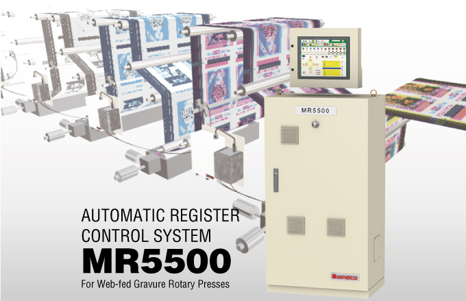
Overview
Built-in communications functions allow the MR5500 to be linked to a quality inspection system to reduce total costs (time, labor, and materials)!
Nireco has built this controller based on many years of experience with control technology. The MR5500 detects register marks using high-performance optical fiber detectors, and controls the printing register to a high degree of precision.
Operation is by touch-screen LCD panel. You can set the system up by following the instructions on the screen.
Feature
-
Can be linked to a Nireco quality inspection system to achieve “integrated management” in the gravure printing process
The automatic MR5500 register control system has built-in communications functions. It can be connected to print quality inspection systems or print still-image devices to achieve integrated information management and smarter operation.
-
The operation panel can be removed and operated separately from the console
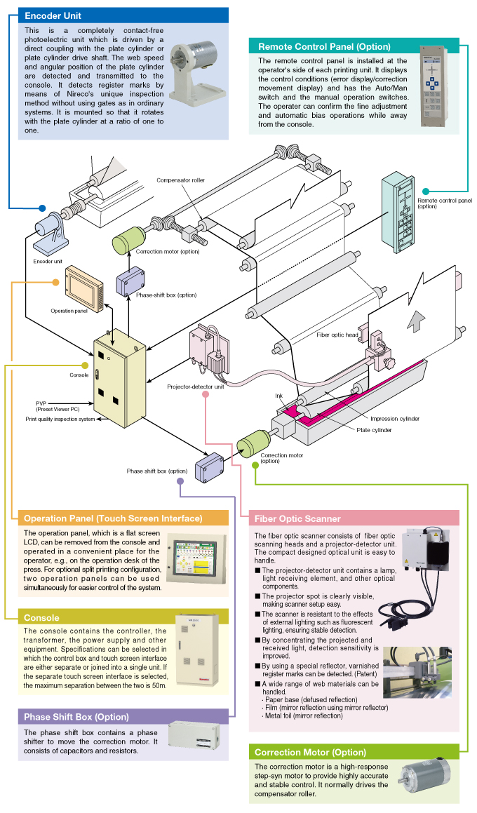
The operation panel, which is a flat screen LCD, can be removed from the console and operated in a convenient place for the operator, e.g., on the operation desk of the printing press.
-
FSP (First Search and Preset) substantially cuts down on the amount of waste created
It has until now been impossible to check for position of initial plate setting before all of the colors start printing. The FSP function makes it possible to check the plate positions after printing only one or two colors, cutting down on the time spend and material wasted during initial set up.
-
Automatic recognition of registration marks
The registration marks are automatically recognized on the moving web.
-
Rapid, optimum corrective action
The optimum predictive control will be provided for each web type.
-
Extraordinarily easy for the operator to use
Every system function can be performed by the operator on the touch screen LCD panel.
A waveform display gives the operator an immediate representation of the registration, even at very low speeds. The display is switchable between sowing the waveform for one complete plate cylinder revolution or the waveform near the gate. Setting the gate is a one-touch operation.
The name of each setting point is displayed when data settings are made.
The icon-based operation is international understandable. -
Different types of marks (vertical and horizontal) and web types are handled by one type of sensor
Registration marks can easily be handled by changing an attachment at the fiber optics scanner.
-
Failsafe function guarantees stable operation
When a major error occurs or when there is a large deviation in registration, such as a missing mark, the fail safe functions activated to maintain an extra margin of registration control.
-
Job memory
Parameter settings can be stored and later recalled when running the same product (up to 1000 data sets).
-
Analog deviation signal output
Deviations signals are output as analog voltage (+/-5V) to allow recording.
-
Applicable with a double-sided and split-printing simultaneously
Configuration
The MR5500 system consists of four main devices: control panel, optical fiber detectors, encoder unit and correction motor.
Only one encoder unit is used, regardless of the number of channels in the system. The encoder is installed so that it turns together with the plate cylinder. An optical fiber detector is mounted on each printing unit. There is one detector for the unit printing the standard color, and detectors for the units printing the second and third colors. The detectors send signals to the control panel. The controlling conditions are input into the setting screen on the control panel in advance. The controller receives these commands, calculates the deviation in the position of the register marks, and outputs correcting signals. The correction motor receives the correction signals from the controller. If the circumferential register control needs to be adjusted, the motor moves the compensator roller to adjust the printing deviation of the color concerned, and ensure that the register mark is in the proper position. In addition, if the lateral register control needs to be adjusted, the correction motor moves the plate cylinder to the left or right to compensate for any lateral shift in the printing position of that color.
Specifications
| Web speed | 10 to 500 m/min |
|---|---|
| Cylinder size | 200 to 2,000 mm |
| Measurement accuracy | ±0.01 mm (mark to mark) |
| Control speed | 1 mm/sec. (in a circumferential direction on the paper path) 0.5 mm/sec (differential gear) 0.5 mm/sec (lateral direction) |
| Fine adjustment range | ±5 mm (in a circumferential direction on the paper path) |
| No. of channels | 2 to 12 channels (8-channel system is standard) |
| Controller power supply input |
|
| Motor power supply input |
|
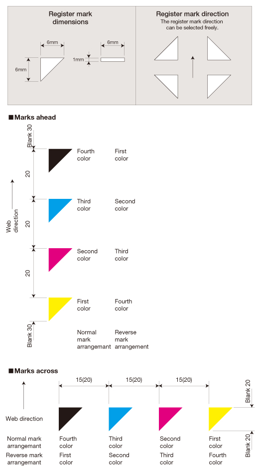
Register Marks
Register ahead and across is measured and controlled using positional information read from specially printed register marks. The register marks, which present the positional information, are determined by their shape and arrangement.
Contact Us
Please use this form to submit your inquiries, feedback and/or requests to NIRECO.
